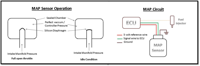
Diagram Map Sensor – A fully functioning MAP sensor is necessary to maintain the right combination of acceleration, fuel economy, emissions and engine smoothness. When the throttle is wide open and air is rushing into . It utilizes two discs of copper clad board with a piece of foam in between for each of 64 sensors. As the foam gets compressed, the capacitance between the two pieces of copper changes .
Diagram Map Sensor

Source : www.youtube.com
Toyota map sensor pinout

Source : in.pinterest.com
MAP Sensor wiring colors | GMC Acadia Forum

Source : www.acadiaforum.net
Sensors

Source : motorsport-electronics.co.uk
MAP Sensor Wiring Diagram: Learn How to Connect Your Car Sensor

Source : www.tiktok.com
Clemson Vehicular Electronics Laboratory: AuE 835 Student Project
Source : cecas.clemson.edu
MicroSquirt® Introduction
Source : www.useasydocs.com
MAP Sensor: Working, Structure and Types Utmel

Source : www.utmel.com
GM 3 bar map sensor calibration G4+ Forums | Link Engine

Source : forums.linkecu.com
MAP Sensor & Wiring Diagram YouTube

Source : www.youtube.com
Diagram Map Sensor MAP Sensor & Wiring Diagram YouTube: Browse 3,900+ mapping diagram stock videos and clips available to use in your projects, or start a new search to explore more stock footage and b-roll video clips. Map of the direction of wind . A ladder diagram consists of two vertical rails that represent the power supply, and horizontal rungs that contain the logic elements. The logic elements can be contacts, coils, timers, counters .